PERSONAL NERF PROJECT
I wanted to create another portfolio project that can help me improve my 3D modeling skills. I chose to model a Nerf blaster after sketching a few designs for the Sketchwars Facebook group. Nerf blasters are a great challenge when it comes to understanding how they work and how they’re put together.
The design should be imaginative and fun.
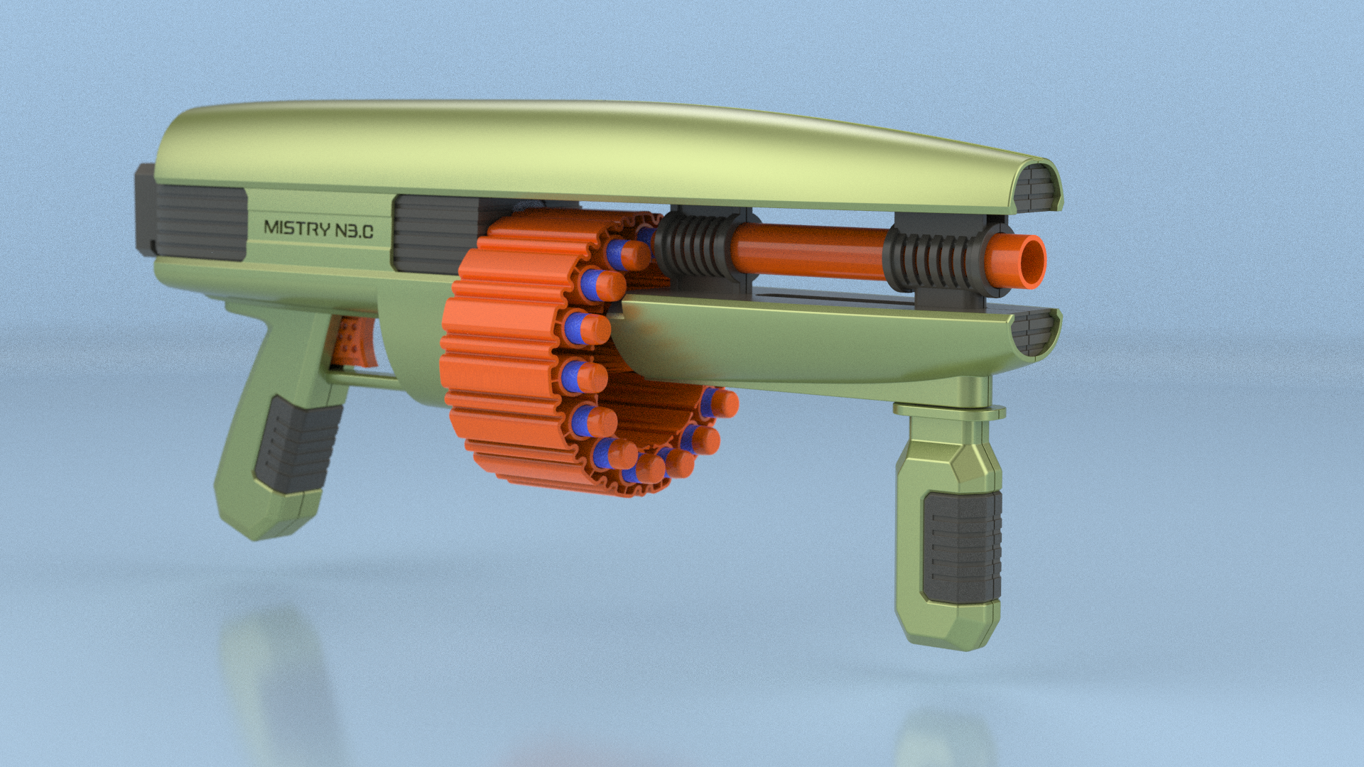
The MISTRY N.30 blaster is a clean, futuristic design taking influence from sci-fi blasters and consumer electronics.
The design features a layered effect, where the colored sculptural housing covers the inner ridged housing. The blaster features a split design revealing the barrel. The overall design is technical, yet rugged. From the feedback I received on social media, I included a receiver that can accept existing Nerf butt stocks.
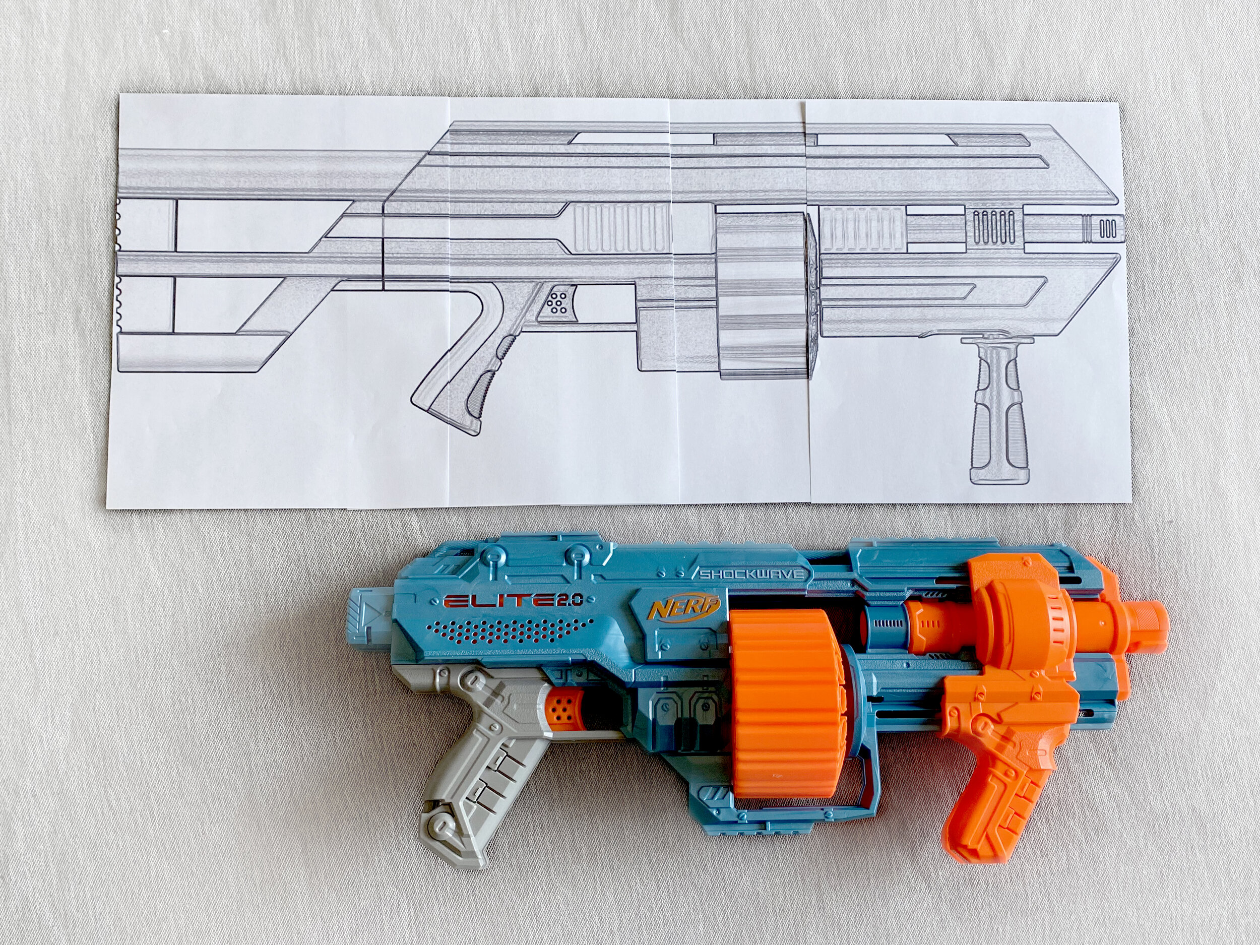
Construction is similar to Nerf’s Elite 2.0 blaster. The left inner housing piece fits within the left outer housing.
Screw bosses and locators within the inner housing piece secures the mechanism.
The right lever stalk attaches onto the left lever stalk. The inner right housing fits onto the left inner housing piece.
Construction is completed with the right outer housing pieces added. The rear grip clip is added.
Everything is then screwed together to complete the clamshell.
Before investing money on a finalized print, I wanted to see a test print of a small component.
I spent $75 using a local resource to make a quick print.
The quick FDM print wasn’t the most accurate print, but was sufficient enough to see proportion, assembly, feel and durability.
I was pleased to see all the parts fitting together with screws and properly fitting with the existing components.
Most FDM printers have a work surface of around 8x8” inches. The inner and outer housings are larger pieces that will have to be printed in halves,
and then superglued together. A prototyper suggested that these pieces could also be milled out of a larger block of ABS.
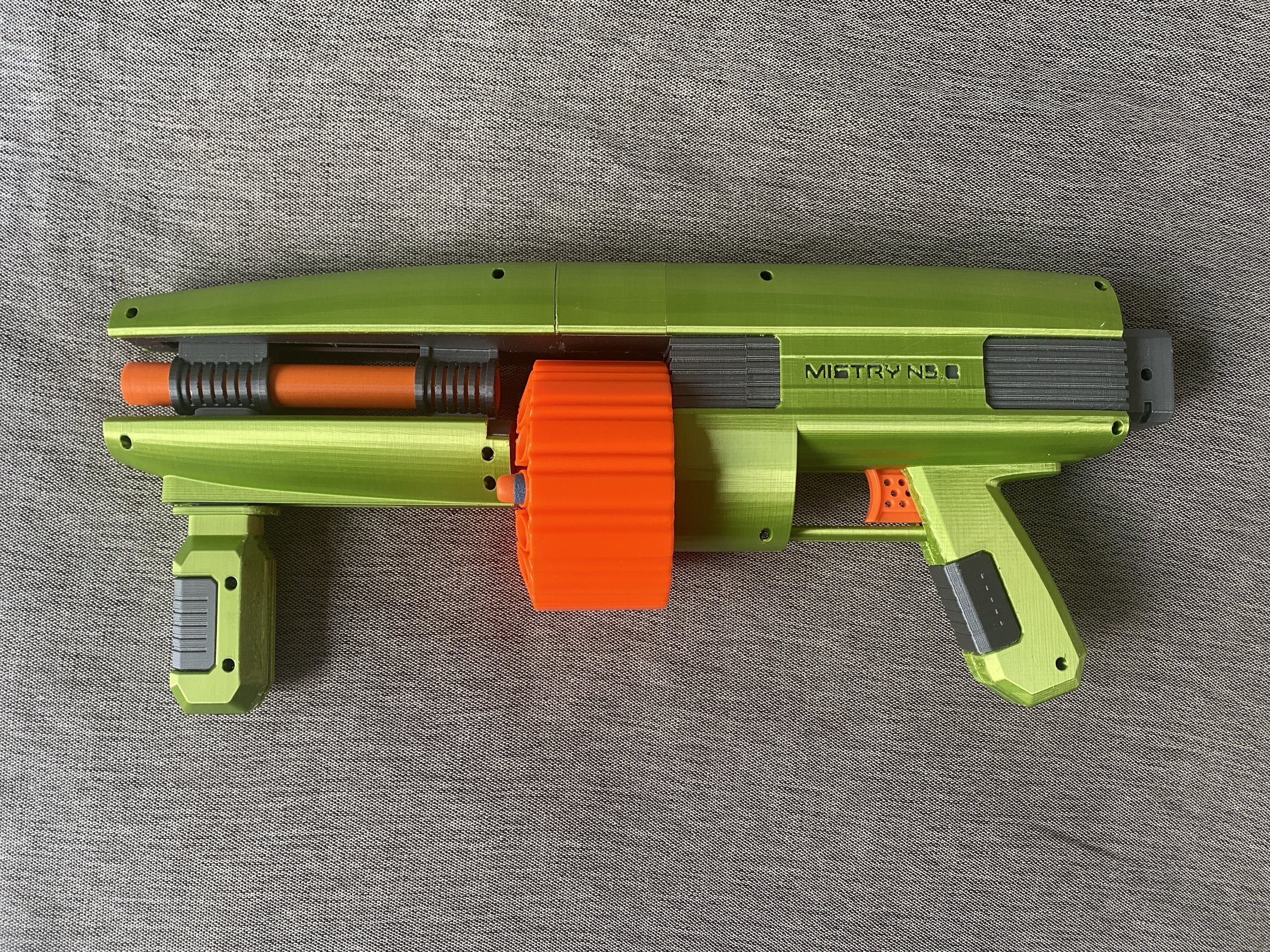
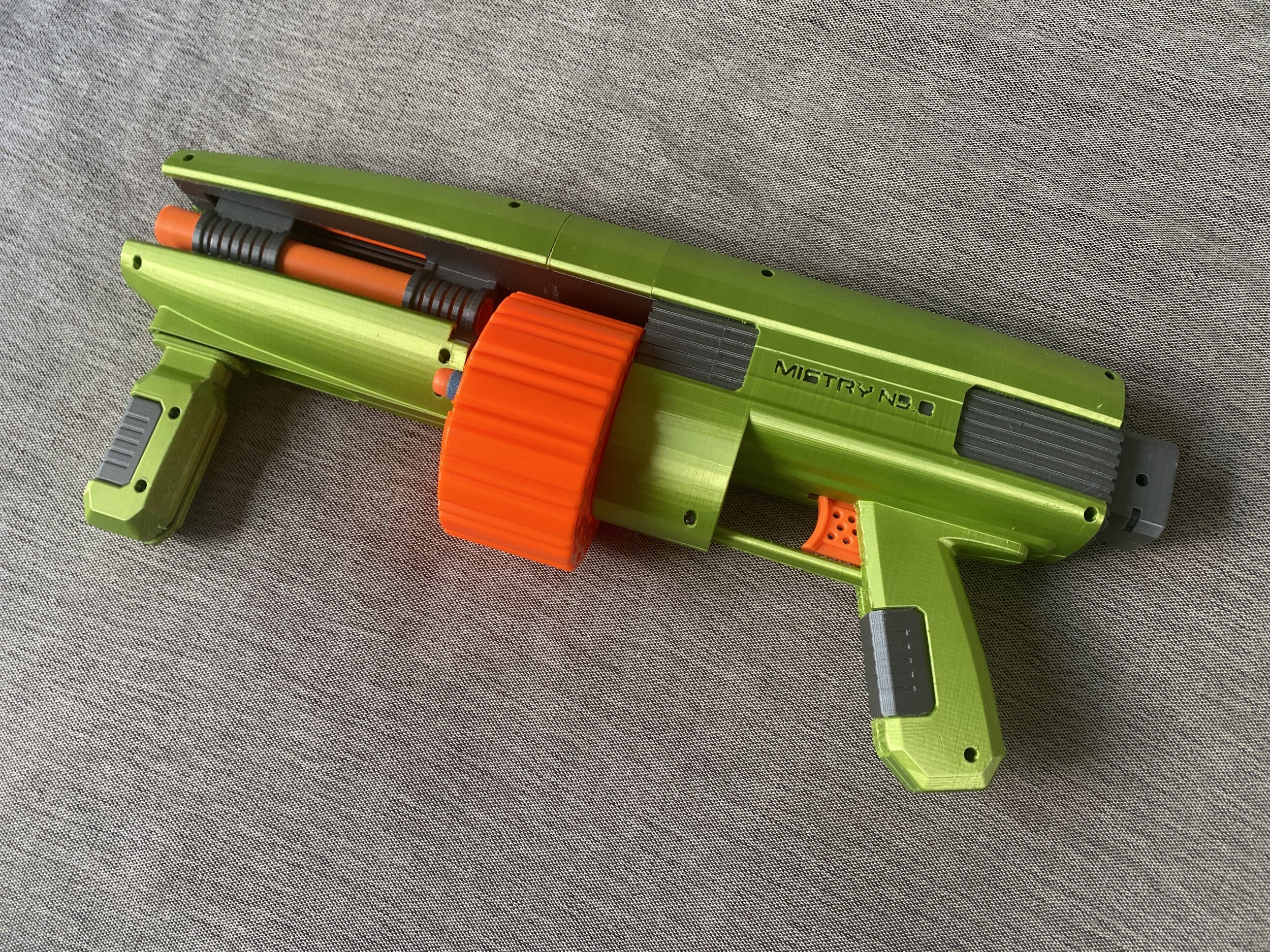
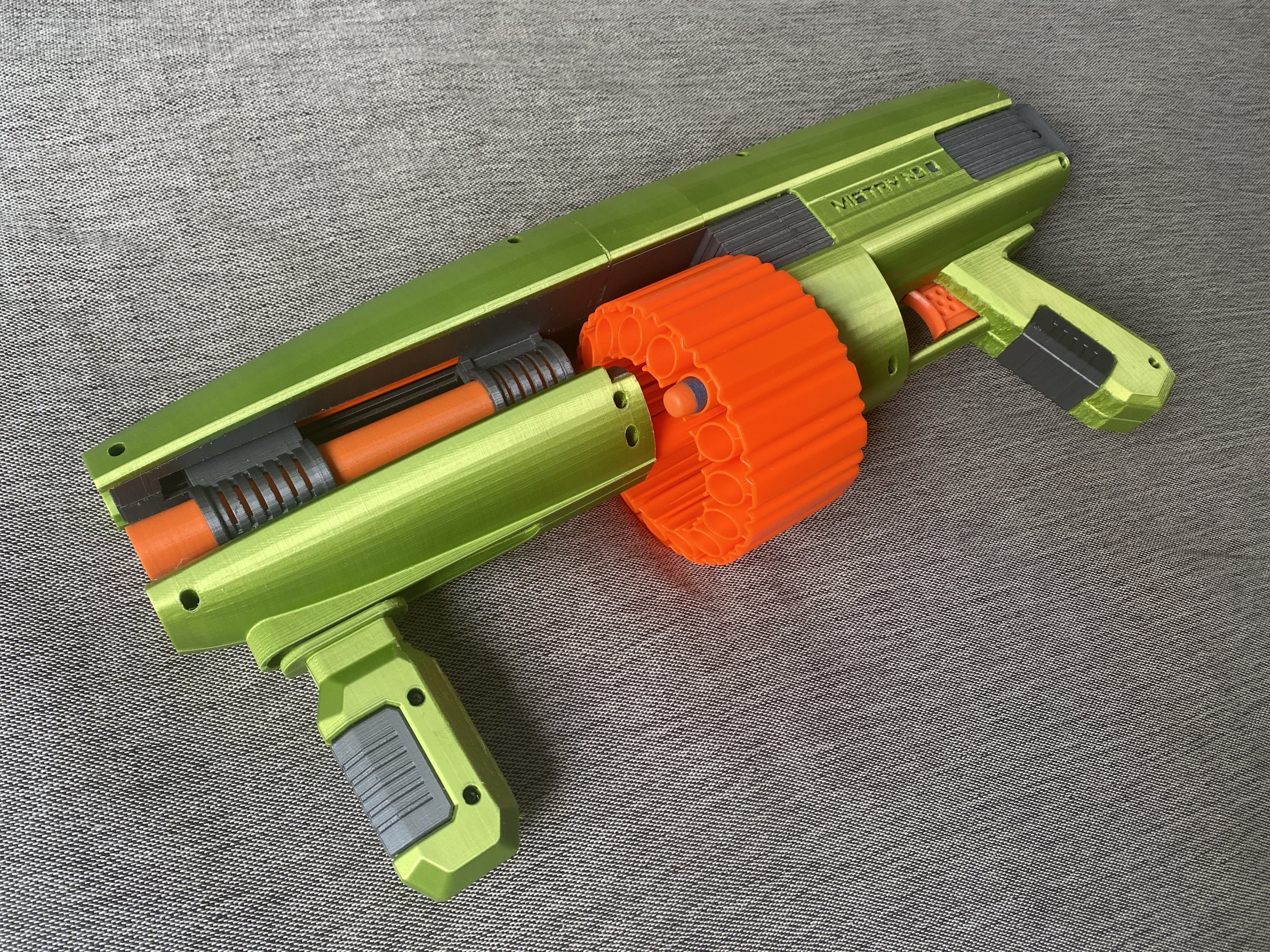
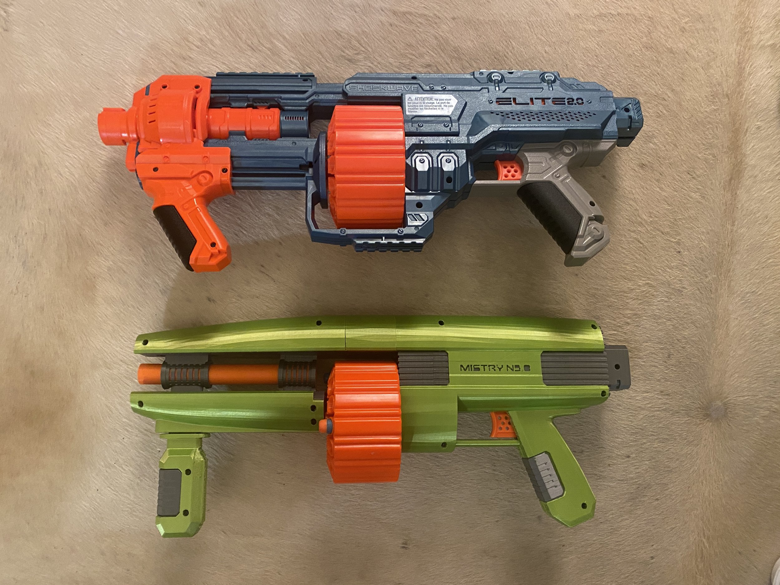
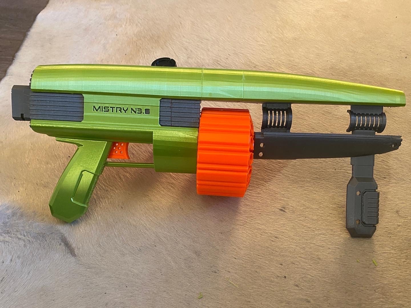
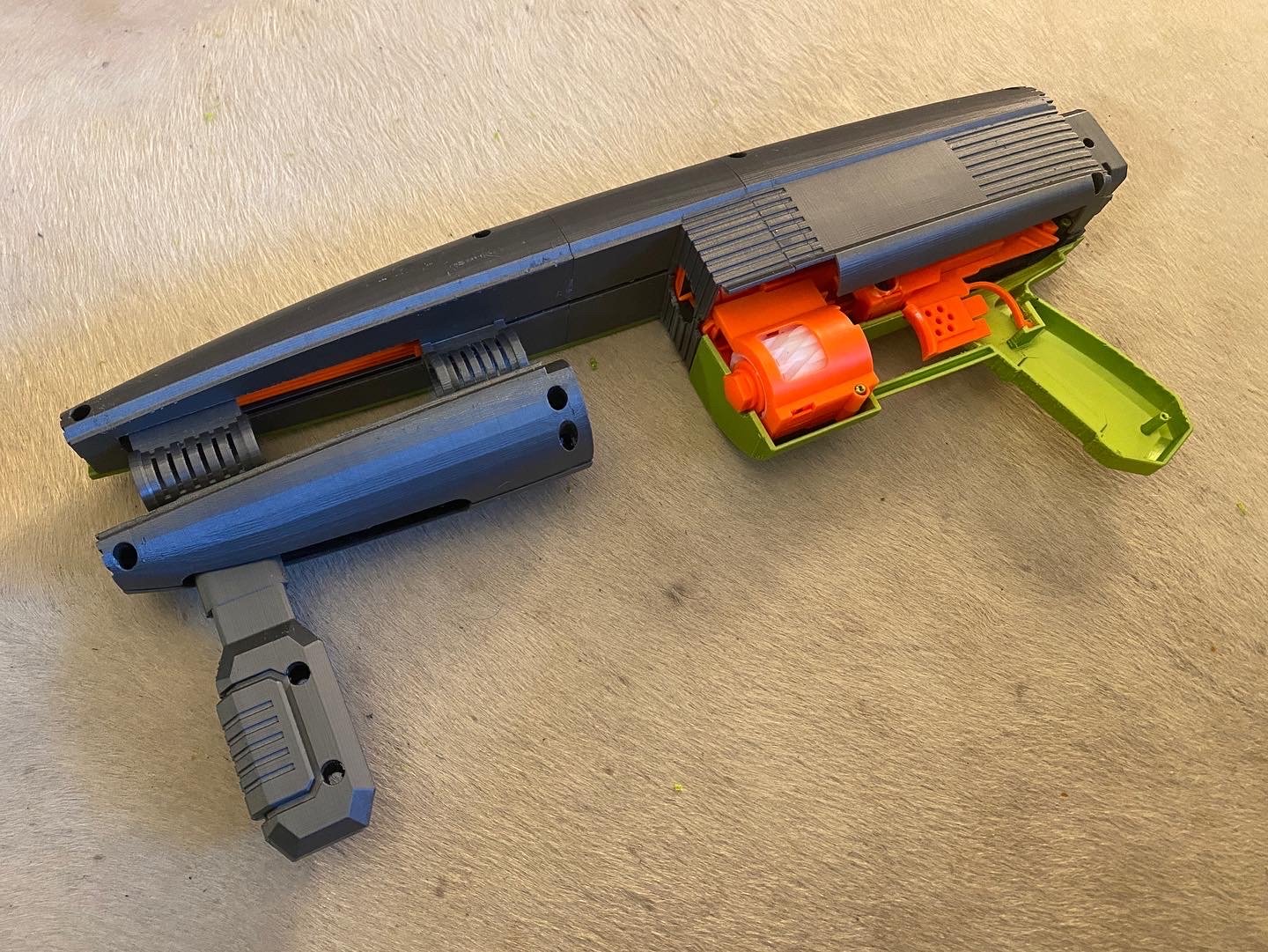
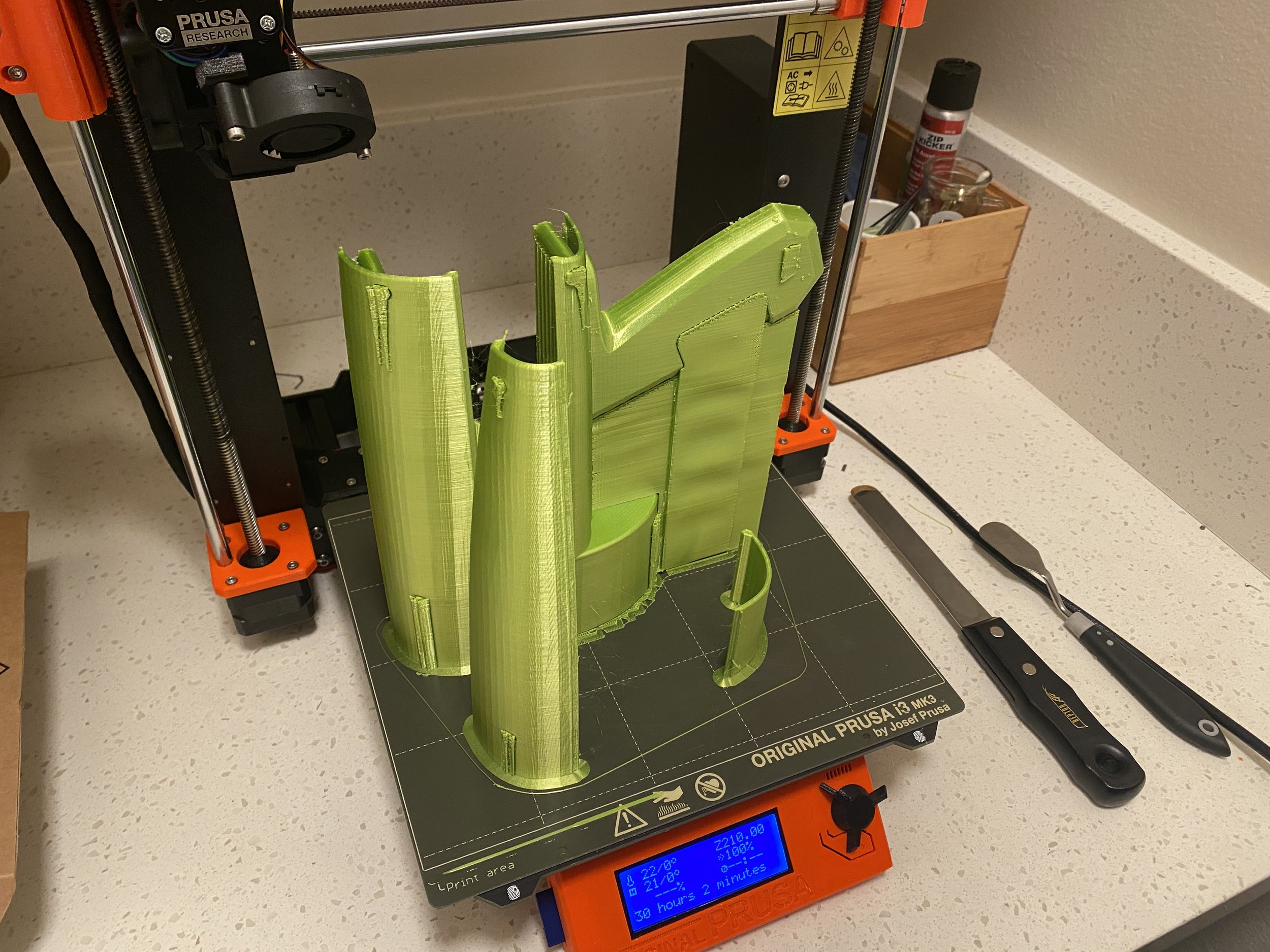
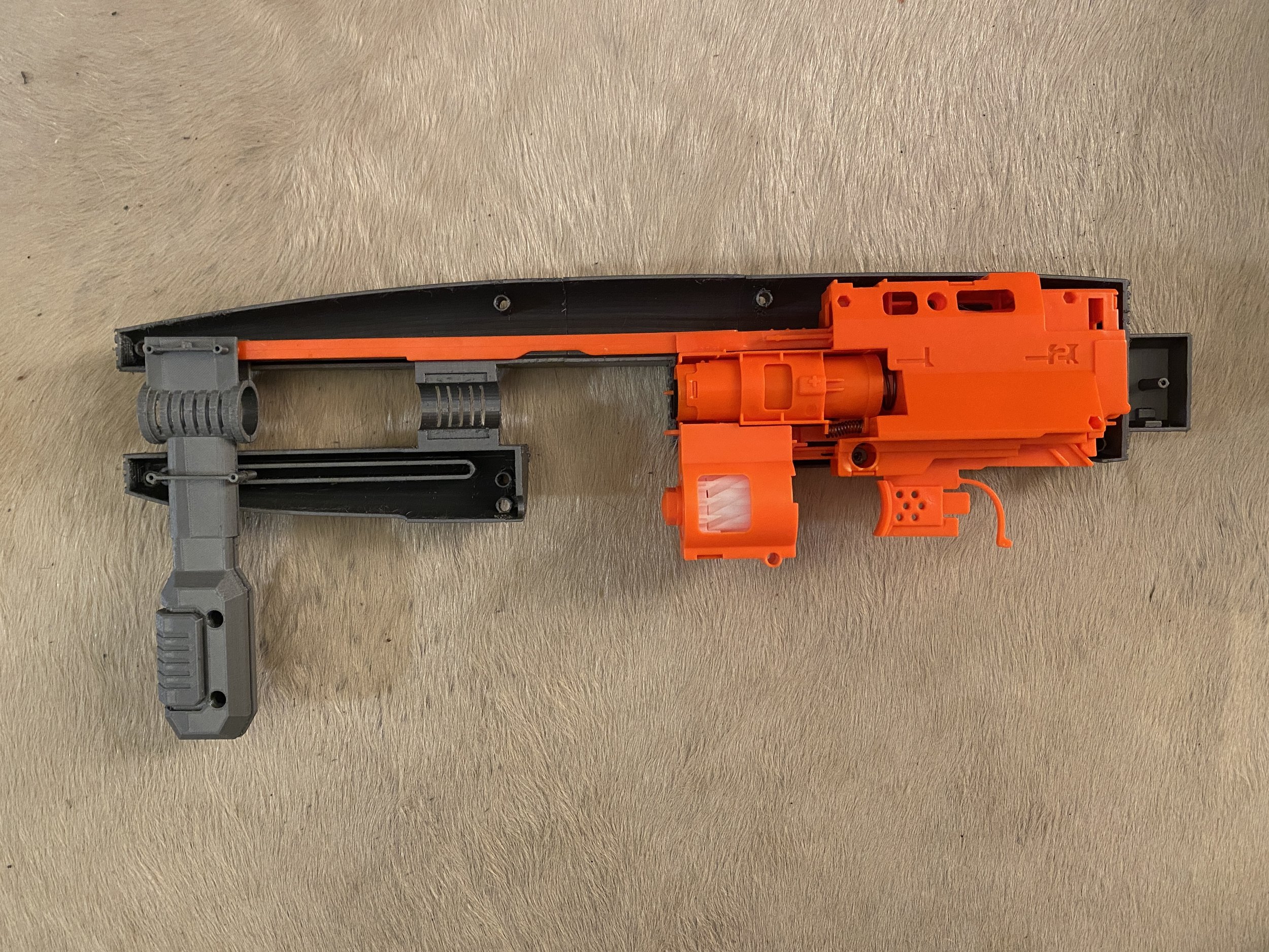
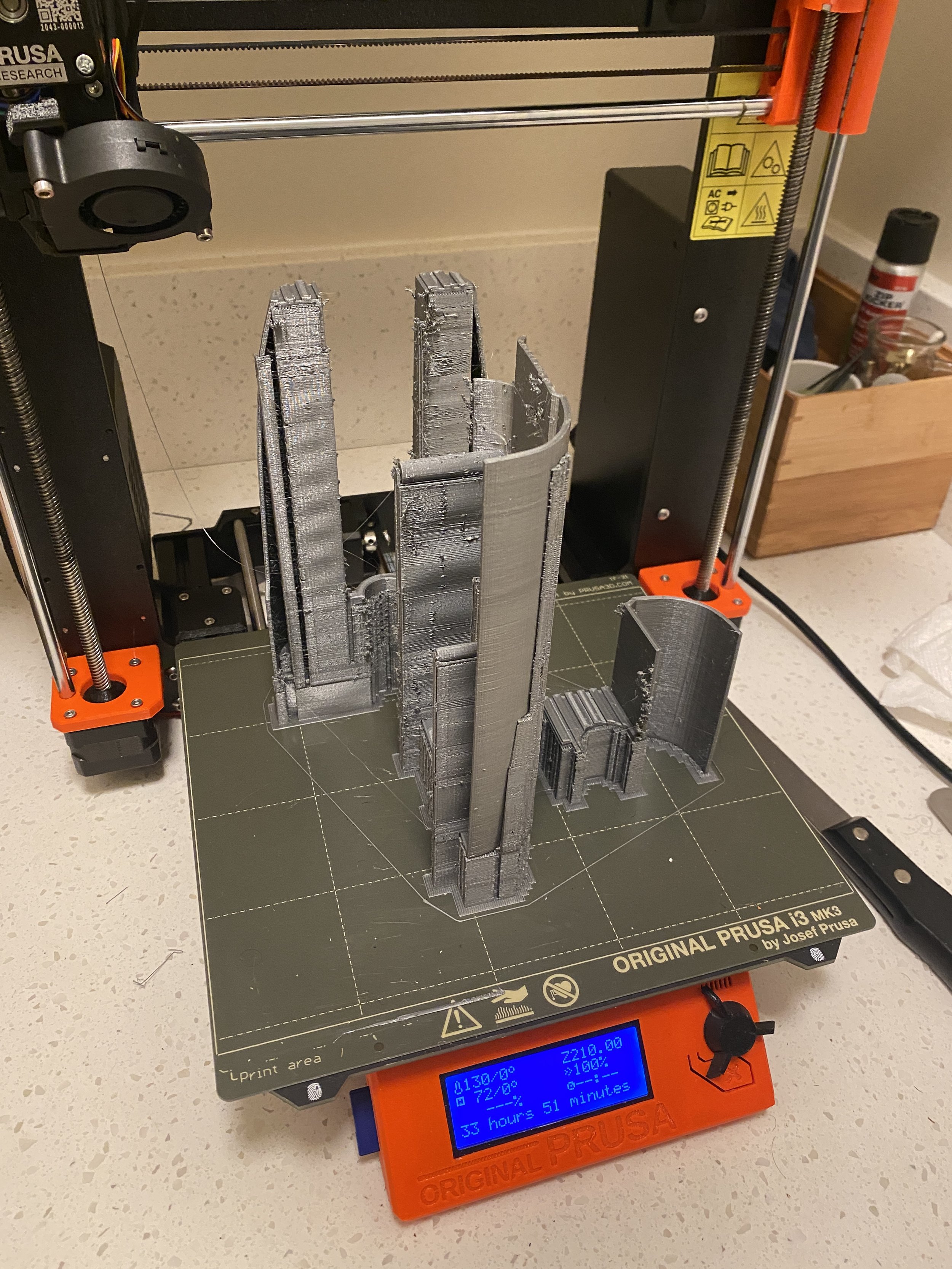
After looking at quotes from model makers, I decided to to invest in a Prusa MK3S+ 3D printer. It took a lot of practice and some failed prints, but the prototype managed to to come together. The lever design will need to be revised, but you discover these issues through making a physical model and testing.
It was very satisfying to hold the design after spending many hours seeing the design in CAD.
INITIAL DEVELOPMenT
The project started out as an entry for the Sketchwars Facebook page. I wanted to suggest a fun project for the week,
and Nerf Blasters was the first thing that came to mind. Before sketching, I decided to look at existing Nerf products.
Initially, I looked at designing around the N-Strike Disruptor pistol. The designs took inspiration from current Nerf products.
It was fun exploring various shape/color variations, but the designs looked more conservative.
A friend recommended sketching silhouettes. This technique was great for exploring different forms.
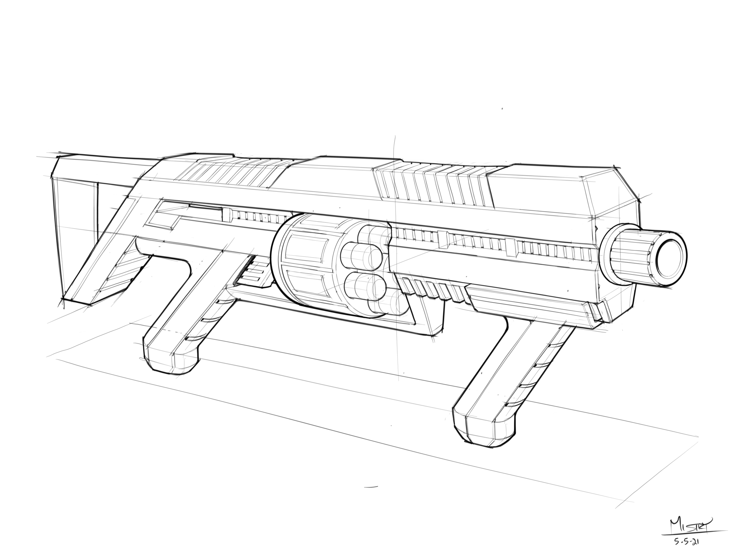
From this exploration, I decided to refine a two handled, pump action design.
I was curious to see my pump action design in CAD. It would be a great exercise in modeling sculptural forms. Before 3D modeling,
I decided to take apart an existing pump action blaster to understand its assembly and how it operates.
After disassembly, I saw that the Nerf blaster uses a mechanism to fire darts from the revolver.
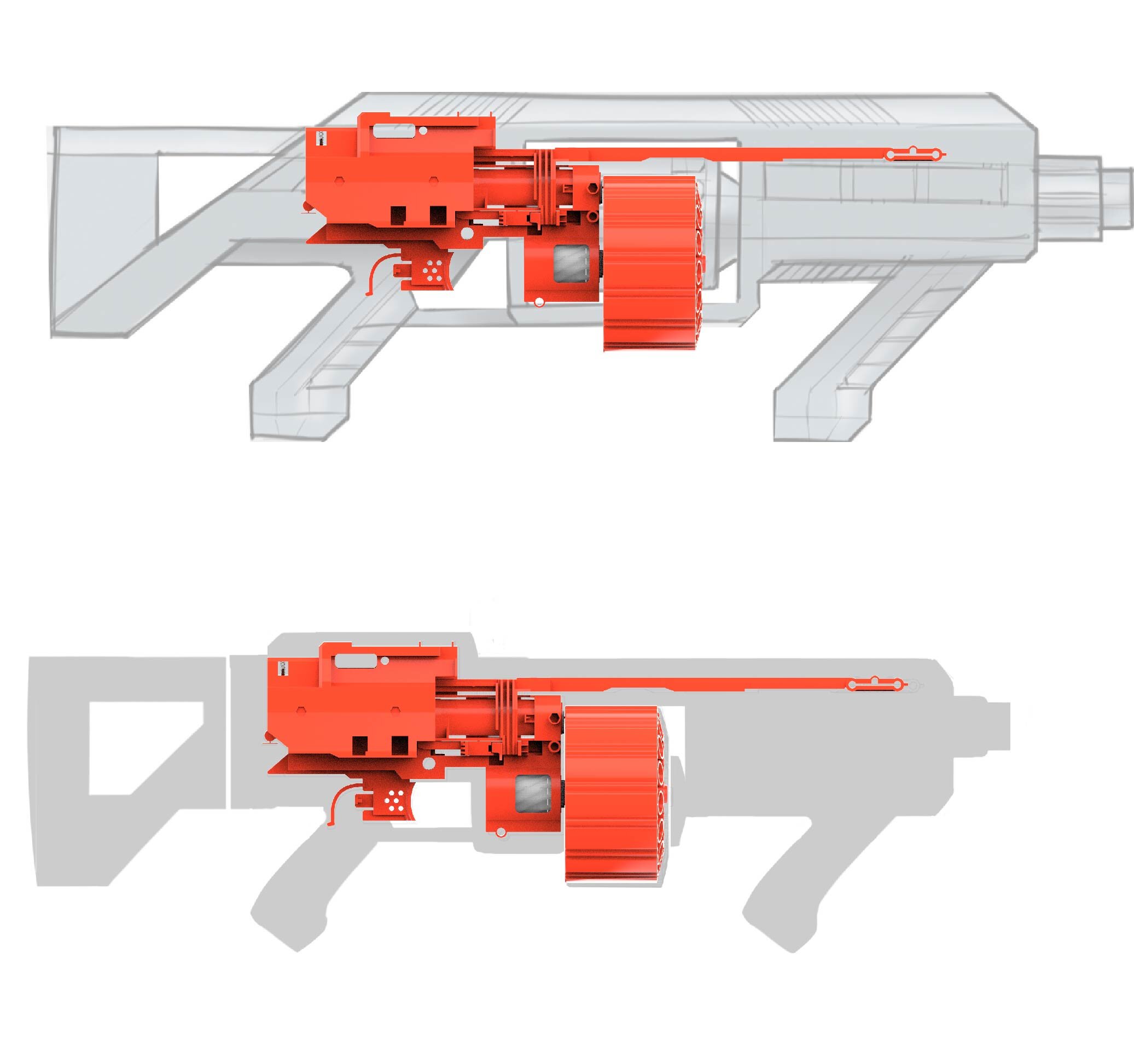
I modeled the mechanism and wanted to see how I can adapt the existing mechanism to my design.
Basic forms were modeled around the mechanism to get a general idea on how this blaster will look.
The initial design in CAD was looking a bit blocky. Silhouettes were sketched to explore different forms.
For a less blockier design, I looked at other forms of inspiration. A friend recommended looking at concept artist E wo kaku Peter.
I also looked at sculptural guns and power tools. This led to two sketch directions. One direction that is softer,
and the other direction being more cylindrical.
The two directions were roughed out in CAD. The softer, more sculptural direction was pursued.
This direction looked less blocky, and features an exposed barrel.
The basic proportion was honed down. The handles included more sculpture and a few details were added to the barrel portion.
The surfaces towards the rear of the blaster were looking a little heavy and needed more development.
Some thought was given to a more interesting handle design and graphic breakups.
During the CAD process, I initially modeled a “C” curve for the body side graphic breakup.
It looked a little odd, so I sketched a version that flowed better with the overall design.
This CAD model was an initial design direction. I was going to modify this design for a 3D print.
Before investing more time into this model, I wanted to gather some feedback.
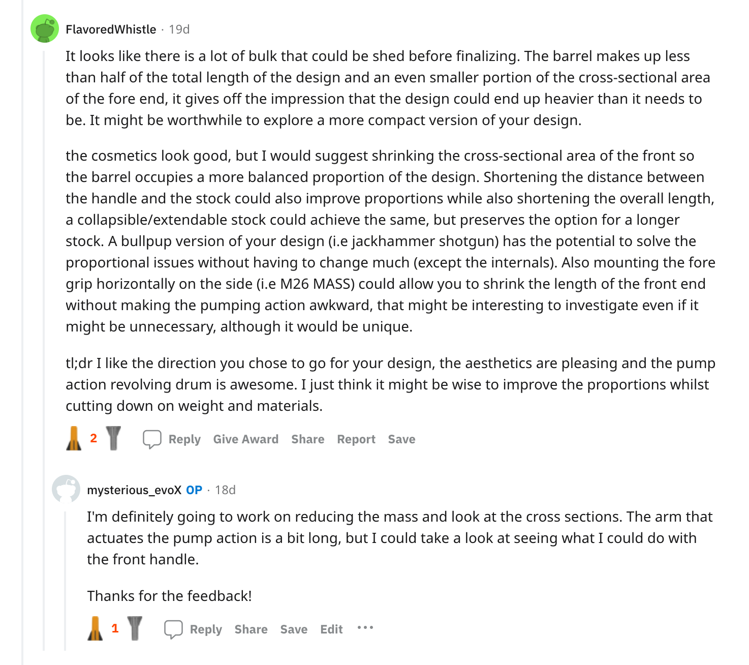
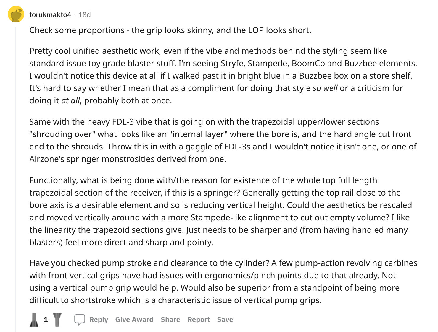
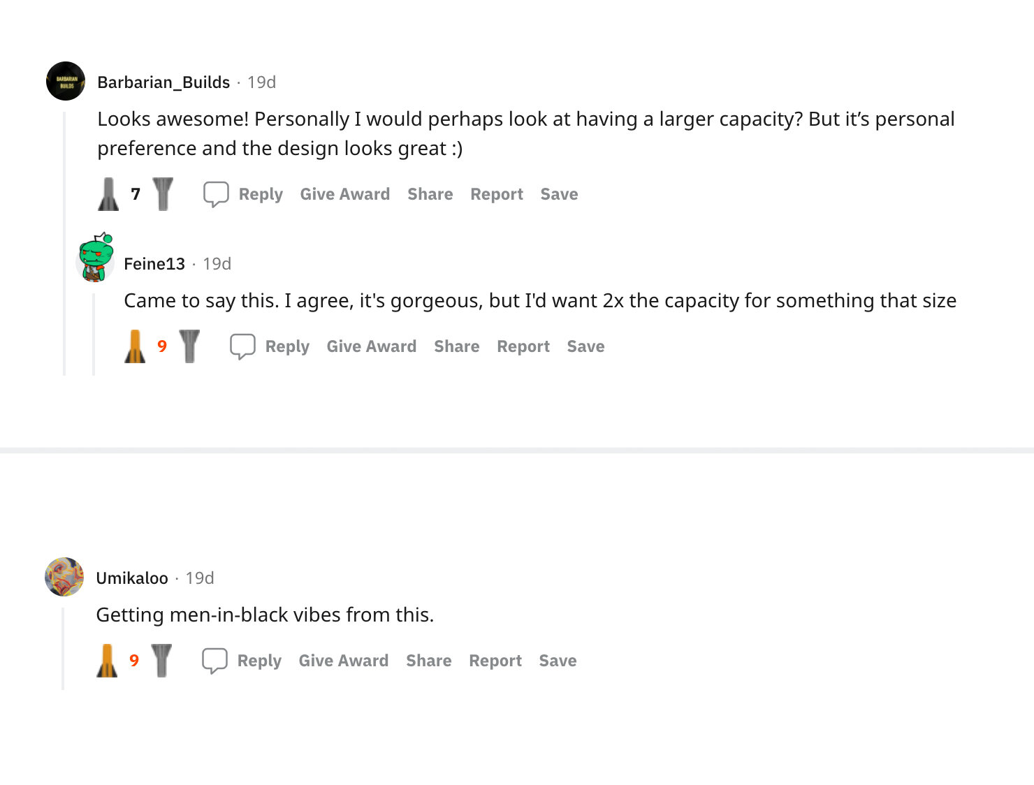
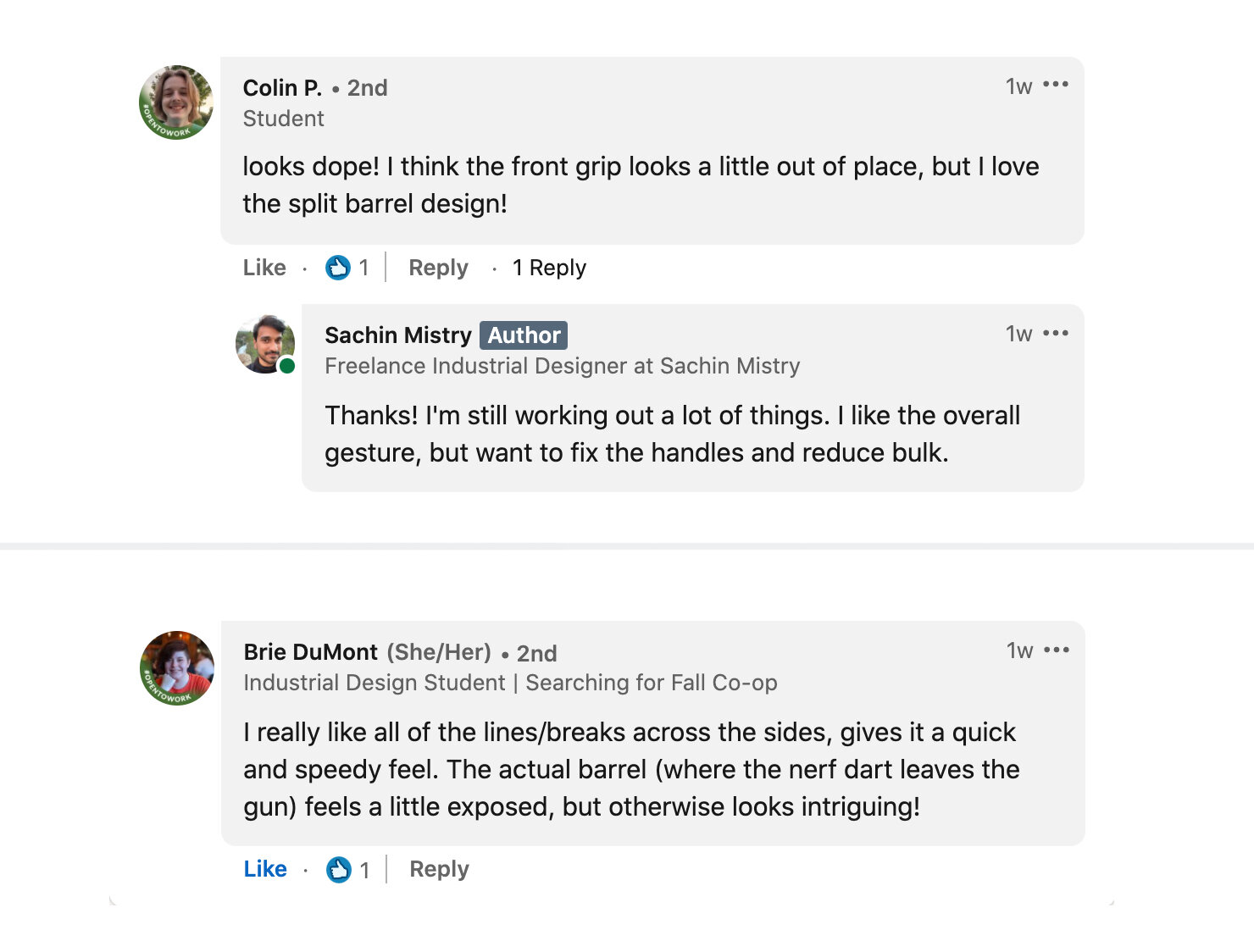
I posted this design on the Reddit Nerf forums, as well as LinkedIn to see what people thought about this design.
The initial reviews were mostly positive. Reviewers mentioned that design was a little bulky and that the handles could be refined.
The reviewers liked the overall sci-fi look of this blaster and the exposed barrel design. With this feedback, I decided to build a new design.
2ND ROUND DEVELOPMENT
After taking in the feedback, I looked at the original design and saw that there was a lot of bulk on the top portion that can be reduced down.
I modeled a basic form that fits tighter to the mechanism.
When looking at a new design direction, I decided to focus on looking at rayguns that are more sleek and futuristic.
The examples from Star Trek have the right aesthetic.
Before investing too much time into 3D modeling, I decided to work on a refined sketch
with more thought about handle design and details.
I decided to colorize the sketch to get a better idea of forms. For the handles, I wanted angular, yet soft forms. The graphic breakups feature
a ridged texture that looks futuristic. The basic idea of the design is captured with this sketch, but will be refined through 3D modeling.
The basic gesture was modeled with consideration to how the housing fits around the mechanism.
I was thinking about graphic breakups and how it can be achieved through part breakdown and construction. The base structure can be black plastic,
while the outer housing can be colored. The user can have the option of being able to paint or customize the outer housing.
Rather than creating an over mold, I wanted to design a substructure that would create graphic breakups.
The outer housing can either be molded color or painted. There will be more development with incorporating clips,
bosses, and screw holes so that the design can be realistically assembled.
This iteration resembles the design sketch, but is a little bulky in some areas. Some tweaks were made in the housing to reduce bulk,
but also provide enough clearance for the mechanism.
This iteration evolved into the finalized design direction. This design features a more tapered shape for the body and added detail for the barrel receiver and handles.
Within Keyshot, more attention was given to CMF. The grip areas feature a textured top surface.
The inner housing features a satin warm dark grey color. The outer housings features a matte green metallic color.
The metallic green looks sci-fi, and highlights the forms.
